Technical specifications
Each puck contains a number of electronic circuits with a small computer. In fact there are four computers in each puck.
The tablet controls the system. The tablet is connected to the orange master puck via bluetooth.
The master puck communicates with the yellow slave pucks via an 868 MHz wireless system. This system was chosen to allow for the longest possible range, thus giving the greatest number of possible uses. If the pucks are placed 50 centimetres above the ground, they will have a longer range than if placed at ground level. In a sports hall this means they can be in contact over the length of a badminton court.
Components
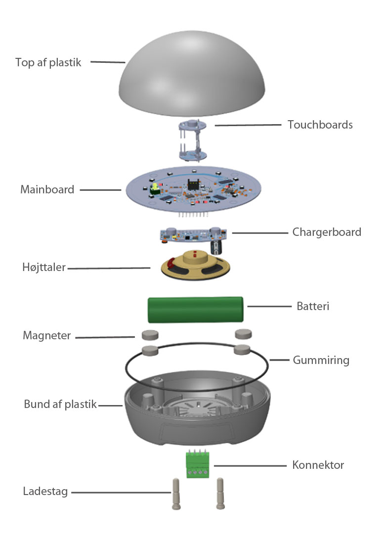
We have exploded a puck to show what it contains.

Plastic Top
The top half is made of ABS plastic, and is the primary contact for users and can take everyday knocks, including falling from a table to the floor. The top is designed and made in Denmark.
Mainboard
The mainboard includes the pucks largest computer which processes radio communication and controls the pucks other parts. these include an accelerometer, an RFID reader, plus touch, sound and light systems.
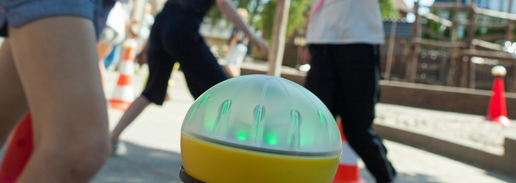
The pucks light system includes 12 RGB light diodes. The total of 36 light diodes can be controlled individually from the mainboards computer.
The mainboard also has an RFID card reader that communicates with cards held close to the puck in the same way as with a travel card.
The mainboard contains an ATMEGA1280 known from the large Arduino - boards. This has an Arduino - boot loader, which can be reached by USB via the green connector at the bottom of the puck.
Speakers
There is a speaker the puck which is one of two response ( output ) systems in the puck.
Magnets
The 4 magnets ensure that the puck sits securely where there is a metallic surface, and which ensures quick set up and packing up.
Plastic bottom
The bottom half is the pucks body, and it is free that the electronics er fixed. The top and bottom are secured with four screws. on the back is found the pucks serial number on a label. The colour of the bottom is orange for the master puck, and yellow for the slave pucks
Charger
The two brass heads at the bottom are to charge the puck from the charging station.
Touch boards
The two touch boards contain the electronic contact with the touch sensors and the infra red system. The sensors work like the screen on a smart phone. The infra red system supplements the touch sensors and comprises three infra red diodes in the top and an infra red sensor which can register reflections from things near the puck. If one system does not work, the other can be tried.
The infra red detector can register light from for example a laser beam. You can mark a finishing line with a laser beam. Note that there are safety considerations with the use of lasers with which you must be familiar, especially when children are nearby.
The touch board includes an ATMEGA168 known from Arduino -boards.
The Charger Board
The charger contains the electronics that allows for the charging of batteries. The board also features an accelerometer which is able to read how the pucks are standing in relation to specific gravity. This function is used for example, to control the on and off function.
The sound system is also found here and can hold up to three minutes sound clips. New sound clips can be uploaded to the pucks.
The Charger Board includes an ATMEGA168 known from Arduino -boards.
Battery
The battery supplies power to the electronics. Under normal conditions the battery can last for up til eight hours. A complete charge up for all parts takes about three hours.
The batteries give 3,7 V.
Rubber Ring
The rubber ring ensures that the puck is watertight in moderate rain. The pucks do not fail if they are outside when it starts to rain.
Please note however that the system is not recommended for outdoors use in rainfall, and that the guarantee does not cover water damage.
Connector
The four legged contact at the bottom of the puck is used when the puck is updated or programmed. The four prongs are similar to an USB connector. The pucks can be charged via a USB using a special convertor.
